Steam Generators for Enhanced Oil Recovery
Steam generators for recovering the highest possible percentage of Original Oil In Place (OOIP) is an urgent concern in today’s political environment — one for which you need the most advanced control system available. At ACES we’ve combined 50 years experience with control systems and 15 with steam generators, and applied them to the challenges of the Enhanced Oil Recovery (EOR) industry.
ACES is ISO 9001:2015 Certified in Design, Development, Manufacture, Installation, and Technical Support on a World-Wide basis for Steam Generation Technologies and Products for the Oilfield Industry.
With our ASME S, National Board Inspection Code, and NB-415 certifications we can build and refurbish Oilfield Steam Generators. Currently we have a new 27 MMBTU under construction, used 50 MMBTU in refurbishment (incl. new convection and control system), And a 30 MMBTU (NOS) recently unpacked from OEM crates and getting prepped for testing. The 30 MMBTU will be upgraded with new wiring and control system. The new Aces wiring system is designed to ease and encourage owner assembly and start up at arrival of its desired location. “Plug and Play”
ACES services and OTSG systems can be found operating in the following countries:
Location Machines Size (Btu/hr)
Canada 5 25 MM to 73 MM Twin Pass
USA 6 10 MM to 85 MM Twin Pass
Mexico 7 25 MM to 32.5 MM
Colombia 3 25 MM to 50 MM
Venezuela 4 25 MM to 32.5 MM
Egypt 1 10 MM
Kuwait 2 30 MM
Introducing the FlexSteam Control System

Accurately predict your steam discharge quality with the FlexSteam Control System.
Whether your generator is 5 or 50 years old, whether you’re outputting 5,000 or 100,000 pounds of steam per hour, we’ve designed a steam generator control system that automates the entire process and enables you to predict your steam discharge quality within very fine tolerances.
Standardized yet Adaptable
With FlexSteam we’ve standardized our control system software to fit any sized generator — and yet there’s plenty of room for customization: Choose to burn natural gas, propane, oil or diesel fuel. Specify your generator size and other variables such as water flow and steam pressure. The FlexSteam Control System offers the quick installation and simple setup you need, while still giving you all the options you want.
Complete Automation

The FlexSteam Control System installed in a Texas generator. We’re currently installing panels in Canada, Egypt and Columbia.
Some of our clients with older generators are amazed at the automation achieved when we install FlexSteam on their machines. “You mash the button and walk away,” said one happy customer, who was accustomed to fiddling with buttons and levers to keep his generators on track. “I can get in my truck and leave, and when I come back it’s still running.” This automation system also has options for emissions tracking and control.
Reduce Fuel Consumption, Increase ROI
It’s not uncommon for our customers to see a 20% increase in fuel-to-steam efficiency after installing FlexSteam. Thanks to higher steam quality, lower fuel costs, emissions control, automation, and ease of use, FlexSteam can pay for itself in as little as a year or two.
ACES Experts can provide Turnkey solutions to renovate the steam generator. All services performed in house or in the field by the ACES Team.
AREAS OF EXPERTISE
- Control system engineering
- Remote system monitoring
- Control panel design and assembly
- Historical data collection
- PLC/PAC/HMI programming
- PLC conversions
- Field instrumentation
- Network architecture (LAN/WAN)
- Maintenance, upgrades, and modifications
- Variable frequency drives
ACES Introduction to Oil Recovery
In 2022 the Global oil production amounted to 93.9 million barrels per day with a projected steady rise in production levels in the future due to newly emerging markets and technologies, and growing populations. However, nearly seven trillion barrels of basic and heavy oil will remain in reservoirs after conventional recovery methods have been exhausted. This has forced the introduction of new methods to improve oil in place (OIP) recovery (total oil content of a reservoir).
1.1 Oil Recovery Stages
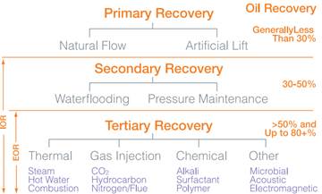
The stages of oil recovery are broken down into three groups: primary, secondary, and tertiary recovery. These three recovery methods follow a natural progression of oil production until a point of low economical profitability is reached. The primary recovery stage of hydrocarbon production includes natural flow and artificial lift techniques. Initially, the reservoir pressure is considerably higher than the bottom pressure in the wellbore. This creates a high differential pressure which naturally drives the oil towards the well and up to the surface. As oil production continues, the differential pressure drops due to a decrease in reservoir pressure. It is at this point that an artificial lift system, such as a rod pump, is introduced to offset the difference. Once primary methods reach an uneconomical threshold, secondary methods are introduced.
The secondary recovery stage of hydrocarbon production includes flooding and pressure maintenance techniques. During the flooding stage, water and/or gas is injected into the reservoir through injection wells. The purpose of secondary recovery is to maintain reservoir pressure and to displace oils towards the wellbore. Gas is typically injected into the gas cap (the free space above the oil), while water is injected into the production zone to extract the oil. Once secondary methods reach an uneconomical threshold, or the injected fluid is being extracted in a considerable amount, tertiary methods are introduced.
The tertiary recovery stage of hydrocarbon production includes methods mainly utilizing thermal, gas injection, and chemical flooding techniques. This stage is synonymously referred to as enhanced oil recovery (EOR). This should not be confused with improved oil recovery (IOR), which is a more general term that implies improving oil recovery by any means.
1.2 Enhanced Oil Recovery
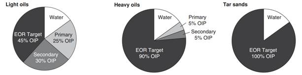
Figure 1.2–A: EOR for Different Hydrocarbons
EOR is more specific in concept than, and can be considered a subset of, IOR relating to tertiary recovery methods. EOR refers to a reduction in oil saturation below the residual oil saturation (Sor). Residual oil saturation is the ratio of the immobile residual oil volume divided by the effective porosity. Reduction in Sor is the only way to recover oils retained due to immobile high viscosities and oils retained due to capillary forces. Capillary forces represent the interfacial tension between two immiscible (non-mixing) fluid phases occupying the same space that must be overcome to initiate flow.
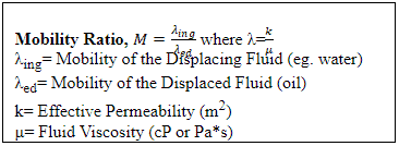
Residual oil mobilization is mainly influenced by two factors: capillary number (NC) and Mobility Ratio (M). The following two equations represent these two factors:
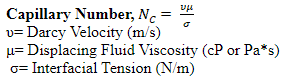
The dimensionless capillary number, also denoted Ca in some industries, is used in fluid flow to characterize the relative effect of viscous forces versus surface tension acting across an interface between a liquid and gas, or between two immiscible liquids. The most practical way of increasing the capillary number is by the application of heat. For a flowing fluid, if NC >> 1, then viscous forces dominate over interfacial forces; the opposite is true if NC << 1. Capillary numbers are relatively proportional to the speed of flow; capillary numbers are large for high-speed flow and small for low-speed flow. A typical reservoir capillary number is in the magnitude of ~10-6.
The dimensionless mobility ratio is a ratio of effective permeability to phase viscosity of an injected fluid divided by that of the fluid it is displacing. The mobility of the displacing fluid and oil is defined behind and ahead of the displacement front (interface between the two fluids), respectively. Mobility ratio influences both the microscopic (pore level) and macroscopic (areal and vertical) displacement efficiencies. A value of M >1 is considered unfavorable because it indicates that the displacing fluid flows more easily than the displaced fluid. This can result in some of the residual oil being bypassed and requires more displacing fluid to reach a given Sor, which lowers the efficiency and cost-effectiveness of the oil recovery system.
1.3 Thermal Recovery
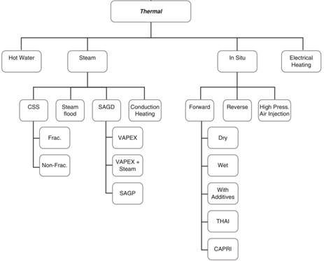
Figure 1.3–A: Thermal Recovery Methods
Thermal methods for EOR have been studied since the 1950s, and are the most advanced among EOR methods when taking field success and technology advancements into account. Thermal recovery is best suited for heavy, viscous crude oils, and involves the introduction of thermal energy or heat into a reservoir to raise the temperature of the oil and reduce its viscosity, thus lowering the mobility ratio. In-situ combustion and steam injection are the most widely used forms of thermal recovery. In-situ combustion involves injecting air into the well and then igniting part of the oil to generate heat internally and produce combustion gases, which both enhance recovery. Steam injection is more widely practiced and is what ACES steam generators are used for.
1.3.1 Steam Injection Methods
Steam injection is the most common form of thermal injection and is comprised of three major styles: cyclic steam stimulation (CSS), steamflooding, and steam-assisted gravity drainage (SAGD). The steam injection method used is dependent upon the depth of the reservoir, the thermal properties of the surrounding formations, and the fluid properties of the in-place oil. These three methods are popular in the US, Canada, Venezuela, and Russia, among other countries.
1.3.1.1 Cyclic Steam Stimulation (CSS)
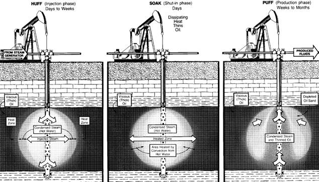
Cyclic steam stimulation, also known as the Huff and Puff method, is a ‘single well’ process consisting of three legs: steam injection, soaking, and production. This method is commonly used when reservoir oil is in the range of 10,000-50,000 centipoise (cP). The initial steam injection period can vary between a few days to weeks and consists of steam being directly injected into a well near the formation base. At this point the well pressure is typically greater than the fracture pressure, and steam extends into the reservoirs via gravity segregation. The well is then shut in for a few days for the soak period to allow heat distribution to occur between the steam and the oil. Lastly, the oil is pumped out of the reservoir over an extended period of time until the oil rate declines to an unprofitable margin, at which point the process is started over again. In high viscous reservoirs the first injection cycle is typically carried out for a shorter period of time than other cycles. This reduces the displacement of certain undesirable materials and increases the output of the subsequent few cycles.
During the onset of a production phase the oil recovery rate increases quickly due to high oil saturation, high increased reservoir pressure, and lower oil viscosity. As time progresses, the reservoir pressure decreases and the oil viscosity increases due to heat losses to the surrounding rock and fluids present in the reservoir. Different factors can influence the length of the production phase time such as the total soak time. If the soak time is too short, more heat is accumulated near the wellbore and is drawn in with the oil when the well is opened. If soak time is too long, heat losses occur in the overburden and underburden layers of rock within the reservoir.
1.3.1.2 Steamflooding
Figure 1.3.1.2–A: Steamflooding Method
Steamflooding, or continuous steam injection, is a thermal recovery method that uses steam generated from above ground which is then injected into the reservoir through specially distributed injection wells. Steam moves throughout the reservoir until it condenses, thereby heating the reservoir oil and reducing its viscosity. The heat also distills light components of the oil, which condense in the oil bank ahead of the steam front, further reducing the oil viscosity. Gas drive of the highly mobilized oil is the principle oil recovery mechanism in this technique. The steam and condensed hot water generate this driving mechanism which draws the oil into the production wells.
Steamflooding is often applied in oil fields with relatively favorable geological conditions, lying at a shallow depth of 700-800 meters. The continuous injection of the steam creates a hydrodynamic connection between the injection well and the production well. However, steamflooding does have its drawbacks. In the past steamflooding has been considered an expensive EOR method due to its relatively long completion time and high operational expenses. Steam breakthrough, sand plugging, and overheating of wells have been known to occur during steamflooding. During breakthrough, steam creates unwanted channels that lower heat and oil recovery efficiency. Sand plugging occurs with the presence of steam turbulence. The steam detaches sand grains and carries them into the well perforations, which causes complications within the tubes. Lastly, an overheated well may have a tendency to negatively affect certain equipment used during the production phase.
1.3.1.3 Steam-Assisted Gravity Drainage (SAGD)
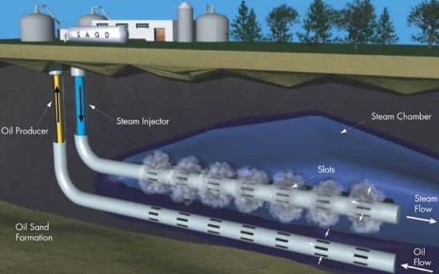
Steam-assisted gravity drainage is used in areas with large deposits of heavy oil and bitumen, such as Alberta, Canada. This process relies on the gravity segregation of steam and consists of a pair of parallel horizontal wells that are placed 4-10 meters apart in the same vertical plane. The top well acts as the steam injector and the bottom well serves as the producer. Steam rises in an up and out pattern forming a steam chamber. This chamber mobilizes the oil, which drains down by gravity and is captured by the producer. Like steamflooding, SAGD is a continuous injection method.
The expanding steam chamber is characterized by two stages: ramp-up and plateau. During ramp-up the initial steam chamber growth happens in an upward direction that occurs much faster than the lateral growth due to the nature of heat to rise. The injection and production rates increase during this time. Once the chamber reaches the top of the reservoir formation, lateral growth takes over and production reaches a maximum (plateau) and slowly declines. Two basic driving mechanisms exist for SAGD: ceiling drainage and slope drainage. Ceiling drainage occurs when the steam chamber is rising and expanding and causes the oil to flow in a countercurrent pattern. Ceiling drainage plays a dominant role in the early stages of the process and is a function of vertical permeability. Slope drainage occurs when the steam chamber is expanding sideways horizontally and plays a more dominant role in the later stages of the process.
2 Generator Components
This section will provide an overview of functionality of components encountered throughout the steam generator. The information presented in this section is a general compilation of possible components on a steam generator. The appearance of many components depends on the style and setup of the generator.
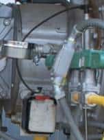
2.1 Air Compressor
Includes: Instrument Air Pressure Switch
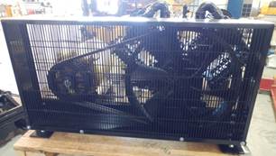
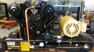
Figure 2.1–A: Air Compressor
The air compressor supplies pressurized air for all pneumatic controls and instrumentation on the generator. The air compressor may be located on the generator skid or at a separate location in which case pressurized air piping will be installed and run to each component. In most cases the air compressor is located near the operator platform around the feedwater pump and motor. However, ACES generators locate the compressor underneath the convection section in order to free up space around the operator platform.
The air compressor is made up of two parts; the motor and the cylinder. The motor electrically drives the attached sheave (slotted wheel that the drive belts sit in) which rotates the larger cylinder sheave. This drives the pistons inside the cylinder in and out creating a vacuum. As each piston retracts, the voided space gets filled with air from around the compressor, which is brought in through the inlet valve. When the piston extends, that same air is compressed and given enough strength to push through the discharge valve while simultaneously holding the inlet valve shut. From there the air enters a storage tank which increases in pressure as the tank fills. Each compressor will have a setpoint pressure. Once the tank pressure reaches the setpoint, the compressor turns off. As air is used by instruments, the pressure will decrease and the compressor will turn on to maintain the tank setpoint pressure. Downstream of the air compressor will be the instrument air pressure switch. This switch will be on the piping before air is split off into the inlet lines for pneumatic devices and ensures there is adequate pressure for these devices to function properly.
2.2 Atomization; Air and Steam
Includes:
- Air Atomization Check Valve (1)
- Air Atomization Pressure Regulator (2)
- Air Atomization Control Valve (3)
- Air Atomization Pressure Transmitter (4)
- Atomization Pressure Switch (Optional)
- Steam Atomization Check Valve (5)
- Steam Atomization Pressure Regulator (6)
- Steam Atomization Control Valve (7)
- Atomization Pressure Transmitter (8)
- Steam Atomization High Stage Pressure Control Valve (Optional)
- Steam Atomization High Stage Pressure Transmitter (Optional)
- Steam Atomization Knockout Drum (9)
- Steam Atomization Knockout Drum Pressure Safety Valve (10)
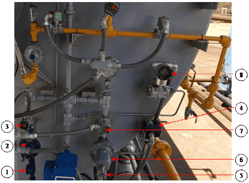
Figure 2.2–A: Atomization Components
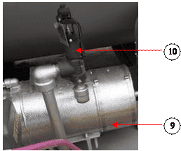
Figure 2.2–B: Steam Atomization Knockout Drum
Atomization is necessary, and will only be installed, when burning any oil or other heavy liquid fuel. Fuel is atomized so that it will readily mix with the surrounding air and burn fully and quickly. Without atomization, the solid stream of fuel would take a long time to completely burn or, if the flow rate were high enough, not burn at all and could accumulate on the radiant floor and start a fire. A steam generator will use both air and steam atomization while running. Initially air atomization is required since steam is not yet being produced. Compressed air will pass through a check valve, pressure regulator, and solenoid control valve. A pressure transmitter will be attached before the regulator to monitor the air pressure entering the regulator. Once the steam has reached quality for an extended period of time, the air atomization will wane off and steam atomization with take over.
During steam atomization, part of the steam exiting the discharge separator will be split off into smaller piping. This piping will continue through a knockout drum where the steam will be separated from any existing liquid water. The steam will exit the knockout drum at 100% quality and travel through a manual shutoff valve, check valve, pressure regulator, and solenoid control valve.
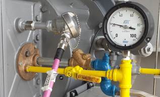
Figure 2.2–C: Burner Atomization Plate
A pressure transmitter will be present on the piping between the air and steam lines. A high- and low-pressure switch can also optionally be installed. For steam generators set up to run at high pressures, there may be an additional high stage pressure control valve to reduce the pressure before the steam enters the knockout drum. In this case, an additional pressure transmitter will also be present to measure the pressure after the control valve. Both the steam and air piping will connect to one pipe which will go to the burner. This piping attaches to a plate on the side of the burner that also has an inlet for the fuel being atomized.
2.3 Burner
Includes:
- Burner Flame Sight Port
- UV Scanner

Figure 2.3–A: Burner Sight Port and UV Sensor
The burner takes in air from the combustion blower and mixes it with fuel from the Pilot or Main Gas line to create heat from combustion. This creates a large flame inside the Radiant Section that promotes radiant heat transfer to the water inside of the pipes running through the Radiant Section. The flame can be as large as 4’ in diameter and 18’ feet long or longer depending on the radiant shell length and the burner. The burner will modulate based off of temperature, quality, and when equipped with an O2 sensor, oxygen concentration in the exhaust stack.
For most generators the desired O2 concentration is 2-4% in the exhaust stack. A lower concentration promotes the forming of undesirable products like CO and NO due to a lack of oxygen atoms needed for creating CO2. Too high of a concentration of air decreases the efficiency of the generator. More excess air means more N2 is traveling through the burner. N2 acts as an inert gas during combustion and consumes heat that leaves the generator through the exhaust stack. Heat that could have been used for heating water is instead used for heating the N2 thereby reducing the efficiency of the generator.
Additional features connected to the burner assembly include the burner flame sight port and the UV sensor. The sight port is attached to the back of the combustion blower chamber and gives a straight sightline through the burner for viewing the flame. The UV sensor is typically mounted on the top of the burner towards the burner throat and is used for monitoring the flame signal.
2.4 Check Valve
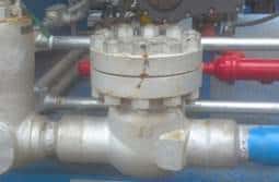
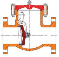
Figure 2.4–A: Swing Check Valve
Check valves are self-contained valves that allow a fluid to pass through in only one direction and are used throughout the water, steam, and air piping on a steam generator. This type of valve relies solely on the flow of the fluid for it to open and close. As flow increases, the pressure against the disc also increases. This pressure will rise until it reaches the cracking pressure at which point the disc will move and allow the fluid to pass through. If the flow rate becomes too low or reverses, the disc will seal the valve.
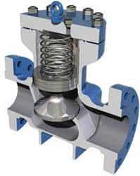
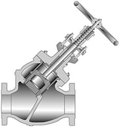
Figure 2.4–B: Lift Check and Stop-Check Valves
Check valves come in many styles but the two most common are swing check and lift check. A swing check valve has a disc attached to a hinge allowing it to swing up into the valve body once the cracking pressure is reached. A lift check valve has a disc which sits in a seat. As the flow rate in the valve increases, the force of the fluid presses against the disc and raises it allowing flow to continue through the valve. A third variant of the check valve used on a steam generator is the stop-check valve (also called a stop-globe valve). This valve is a combination of a globe valve and check valve. In a normal globe valve, the valve stem is permanently affixed to the globe disc while in a stop-check valve the stem head floats in the globe disc. This style of check valve has two purposes: isolate or regulate flow and prevent reverse flow. Stop-check valves are used as the pre-heater and bypass control valves on the outlet of the convection section piping.
2.5 Combustion Blower
Includes: Burner Air Intake
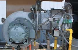
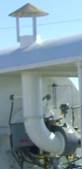
Figure 2.5–A: Combustion Blower and Air Intake
The air intake is located on the operator’s platform above the burner and is the inlet piping for the combustion blower. The air intake is typically covered with a cap to deter water and other objects from entering the combustion blower. The combustion blower and motor make up the back half of the burner assembly and is where the air intake attaches to. As the blower motor spins the combustion blower, ambient air is drawn in from the air intake and expelled through the burner where it mixes with fuel to promote a more ideal combustion environment. The amount of air flow is regulated by a VFD, damper, or both. The combination of these regulators increases the generator’s efficiency and can reduce the production of unwanted combustion byproducts like CO, NO, and NO2.
2.5.1 Fuel Gas
Includes:
- Burner Diffuser
- Fuel Distribution Ring

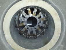
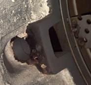
Figure 2.5.1–A: Diffuser and Fuel Distribution Port
Air enters the combustion blower and travels through the body of the burner. At the end of the burner throat, where the burner bolts to the generator, there will be a metal ring. This is the fuel distribution ring. Fuel gas exits this ring through fuel ports where it meets the air and they collectively travel through a diffuser plate. These ports can have covers on them to limit the BTU input of the burner by limiting the amount of fuel that passes through. The diffuser plate is a circular assembly of metal arms with small holes in them that extend in front of the exit ports on the fuel distribution ring, and is used to promote mixing of the fuel and air.
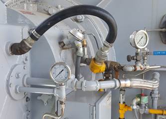
Figure 2.5.1–B: Pilot Air Supply
The fuel distribution ring will not be used until the step to light the main flame is reached. Prior to this, a separate air stream will connect to the pilot fuel line and the mixture will pass by the spark ignitor and through the flame extender. Initially the flame will be small since the burner will be running off of only the gas flowing through the Pilot line. Once the control system determines the pilot flame is lit, the Main line will open and flood the distribution ring with gas. After the main flame is lit, the Pilot line will close and fuel and air will be modulated to reach and maintain quality. See Section 2.12 and Section 2.13 for additional information on the Main and Pilot fuel lines, respectively.
2.5.2 Fuel Oil
Includes:
- Fuel Nozzle
- Burner Gun
- Burner Gun Heater
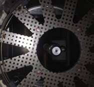
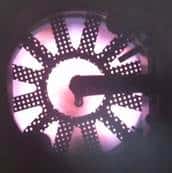
Figure 2.5.2–A: Fuel Nozzle
Air enters the combustion blower and travels through the body of the burner. Like with fuel gas, there will be a diffuser plate at the end of the burner throat. Oil and air or steam will be mixed upon entering the burner atomization plate as shown in Figure 2.2–C. The mixture will enter the burner gun and exit through the fuel nozzle, which is used to atomize the fuel. The fuel nozzle exits in the middle of the diffuser plate so the atomized fuel immediately mixes with the incoming air.
2.5.3 Burner Hinge Switch
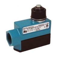
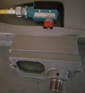
Figure 2.5.3–A: Burner Hinge Switch
The burner hinge switch is typically located on the top side of the burner where it connects to the burner throat or where it swings apart for maintenance. This is a normally open limit switch used for keeping the generator from running while the burner is out of its normal operating position. The switch is a hard metal casing, which contains the wiring, and has a metal pushbutton switch on one side. During normal operation the burner door compresses the switch. Should the door be opened, the switch is disengaged and the circuit is broken which shuts down the generator and prevents it from starting until the circuit is made again.
2.5.4 Burner Oxygen Sensor
Includes: Flue Gas Recirculation
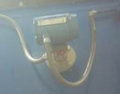
Figure 2.5.4–A: Burner Oxygen Sensor
The Burner Oxygen Sensor is used to measure the O2 concentration at the burner. This sensor will only be present when flue gas recirculation (FGR) is used. FGR takes gas exiting the exhaust stack and circulates it back to the front of the generator where it is mixed with incoming combustion air. The mixture then passes through the burner for combustion. The burner oxygen sensor will measure the current O2 levels entering the burner and, if the FGR damper is controlled with a VFD, send the signal back to the PLC for controlling the damper position.
FGR is used for lowering NOx emissions in two ways. Firstly, mixing flue gas with combustion air lowers the oxygen content of the mixture which hinders the formation of NOx components since there is not an abundance of O2 present. Secondly, flue gas is mostly H2O, CO2, and inert N2. Adding these back into the combustion process lowers the peak flame temperature. Since NOx components are rapidly formed at high temperatures, lowering the flame temperature greatly reduces the formation of them.
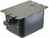
2.5.5 Ignition Transformer
![]()
Figure 2.5.5–A: Ignition Transformer
The ignition transformer is mounted towards the front of the burner and connects to the spark ignitor via a cable. The cable screws on to the transformer terminal and snaps on and off of the end of the ignitor. The ignitor is screwed into a tube that connects to the pilot fuel pipe right before the pipe enters the burner. While the pilot is attempting to light, the transformer sends a high voltage charge (typically 8,000-10,000 volts) through the ignitor. When the charge reaches the terminal point at the tip of the ignitor, an electrical arc is created between the ignitor tip and the pilot fuel pipe. This arc then ignites the pilot fuel stream and creates the pilot flame. The transformer and spark ignitor will only used when lighting the pilot flame.
2.6 Control Valves
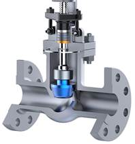
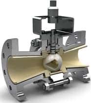
Figure 2.6–A: Sliding Stem and Rotary Control Valves
Control valves are used to control the flow of fluids by varying the size of the flow passage as directed by a signal from a controller. The valve is made up of three parts: the body, actuator, and positioner. The control valve body contains the modulating element and is where the fluid passes through. The modulating element comes in two main forms: sliding stem and rotary. Sliding stem elements, such as globe valves, have a steam and a seat. The stem sits in the seat and is connected to the actuator which drives it up and down. Rotary action elements, such as ball valves, sit in the seat at all times and rotate laterally while connected to the stem. Each rotary piece has a hole through the middle so as it rotates more of the opening is exposed and more fluid can flow through it.
The actuator is attached to the top of the body, connects to the valve stem internally, and is what provides the motion of the valve. Actuators are driven by hydraulic, pneumatic, mechanical, or electrical sources; however most steam generator control valves will be electrically or pneumatically operated. The positioner is used to deliver pressurized air to the actuator in order to move the actuator to the correct set point. An analog I/P positioner is the most common style for modern control valve systems. The positioner reads a 4-20 mA electrical current signal (I) and converts it to a pneumatic pressure signal (P). This output signal then drives the actuator to the correct position.
2.7 Convection Section
Includes:
- Bare Tubes
- Convection Pressure Gauges
- Convection Side Covers
- Solid and Serrated Finned Tubes
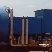
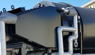
Figure 2.7–A: Convection Section Styles
The convection section is made up of the convection box and the tubes inside. The convection section is located in-between the radiant section and the exhaust stack and is used to capture heat from the exhaust gases and transfer that heat to the incoming feedwater before the water enters the radiant section. This increases the efficiency of the steam generator by reducing the amount of excess heat being exhausted to the atmosphere, and typically contributes 15-35% of the total absorbed heat for the steam generator. The convection box can come in a number of shapes and configurations, but the operating principle is the same for each style.
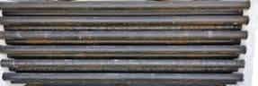
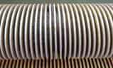

Figure 2.7–B: Bare, Solid, and Serrated Tubes
Inside the convection box are rows of bare and finned tubes that are used to transfer heat from the hot gas to the water inside the tubes. Hot combustion gas exits the radiant section and flows over an initial few rows of bare tubes (shock tubes). These bare tubes shield the finned tubes from direct radiant heat to protect the fins from the high temperatures of the entering gas. Without these tubes, the fins can get too hot and a portion of the fin tips can burn off. Finned tubes come in two basic styles: solid and serrated. Solid tubes are one solid long helically wrapped piece of metal around a circular pipe while serrated tubes have the same helically wrapped metal but the metal is separated to produce rows of rectangular fins.
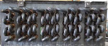
Figure 2.7–C: Return Bend Ends
Figure 2.7–D: Tube Layout Styles
The ends of the tubes are all interconnected into one long coil using return bends, which are located on two sides of the convection box and are covered with removable doors. The doors are only removed in order to replace broken tubes or return bends. The rows of tubes can either be arranged in a staggered or inline layout. Staggered layouts shift over every other row so the tubes are between the rows below them, while inline layouts have all the rows aligned in straight rows vertically. Staggered layouts are more practical for steam generators because they required less space, and facilitate better contact time and turbulence for the exhaust gas passing through
2.8 Differential Pressure Transmitters
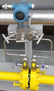
Figure 2.8–A: Differential Pressure Transmitter
Differential pressure transmitters (DPT) measure the difference in pressure between two points and send an analog input signal back to the PLC. Each DPT used on a steam generator has three parts: the body, the manifold, and the orifice plate. The body of the DPT is where all the sensing takes place and is connected to the manifold. The manifold contains three valves and two vent plugs that are used during calibration of the device. Two tubes extend from the manifold into the flanges between which the orifice plate sits.
The orifice plate creates a drop in pressure which is read on both sides of the plate. Inside the body of the DPT is a diaphragm. This diaphragm will flex if there is any difference in pressure between the upstream and downstream sides of the orifice plate. This change is sensed by the DPT and is converted to an electrical signal via differential capacitance which is then sent back to the PLC. A higher flow of fluid creates a larger pressure drop and therefore a larger differential pressure. For gas and water this value is used when calculating and monitoring flow rate. For steam this value is used when calculating quality. See Section 2.17 for more information on orifice plates.
2.9 Exhaust Stack
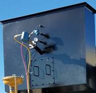
Figure 2.9–A: Differential Pressure Transmitter
The exhaust stack is connected to the outlet of the Convection Section and is where all of the exhaust gas escapes the steam generator. The exhaust gas will mostly be made up of H2O, CO2, O2, and N2 and; after leaving the convection section, will be cooled to a few hundred degrees. Most steam generators will have a temperature transmitter and an O2 sensor on the back side of the exhaust stack for monitoring and adjustments.
The temperature of the exhaust gas is directly related to the flow and temperature of the water going through the convection piping. If the convection inlet temperature is too high then less water should be allowed to travel through the feed water pre-heater. This will lower the convection water inlet temperature and more heat will be transferred to the water in the convection section due to the larger starting temperature gradient. The opposite is true if the exhaust temperature is low. A high exhaust temperature indicates poor generator efficiency because any heat leaving the exhaust stack is a loss, but a low temperature could indicate that the convection section is producing condensation on the finned tubes and damaging them.
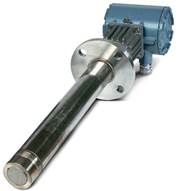
Figure 2.9–B: Oxygen Sensor
The O2 sensor measures the oxygen concentration in the exhaust stack which will ideally be 2-4%. Lower concentrations of O2 indicate that not enough excess air is being added for combustion. Not using enough excess air limits the combustion process since there are not enough oxygen atoms to favor the production of H2O and CO2. Higher concentrations indicate that too much excess air is being used which lowers the efficiency of the generator. Since air is mostly nitrogen and nitrogen is inert during combustion, having too much excess air means that extra energy is being used to heat the nitrogen present rather than being transferred to the water in the radiant pipes. The O2 sensor combats these problems by sending a signal back to the PLC. The controller then interprets what action is needed and sends a signal to the blower VFD so it can speed up or slow down the combustion blower.
2.10 Feedwater
![]()
Figure 2.10–A: Pulsation Dampener
The feedwater system includes all piping and equipment used with water before entering the convection section. Water enters the system and travels through an inlet stabilizer. Positive displacement pumps (like the feedwater pump) contain an inlet valve that continuously opens and closes, creating an acceleration and deceleration of fluid into the pump. The inlet stabilizer (pulsation dampener) minimizes pressure fluctuations created from this to stabilize the flow pattern at the pump inlet which helps to extend the service life of the pump. Inside the stabilizer is either a membrane or a bladder filled with pressurized gas. As turbulent water enters the stabilizer, the gas filled membrane or bladder absorbs the excess energy and returns the water to a more laminar flow pattern
2.10.1 Feedwater Pump
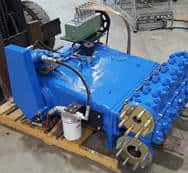
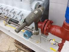
Figure 2.10.1–A: Feedwater Pump and Safety Valve
The water exits the inlet stabilizer and enters the feedwater pump. The feedwater pump can be either centrifugal or positive displacement, but positive displacement is the most common for steam generators since the water flow rate is directly related to the RPM of the pump allowing for easy flow rate calibration. When a centrifugal pump is used, an extra control valve is needed to control the flow rate. A centrifugal pump creates pressure from the flow rate; the higher the flow rate the higher the pressure. Do to this, to maintain a constant pressure but decrease the flow rate downstream of the pump, a secondary pipe is split off of the main line after the discharge dampener. This pipe recycles water back to the suction side of the pump. How much water is cycled back is controlled by the feedwater pump bypass control valve. Attached to the pump is a pressure safety relief valve. This valve connects the discharge of the pump to the pump suction in order to prevent over pressurization from occurring.
2.10.1.1 Feedwater Pump Belt and Sheaves
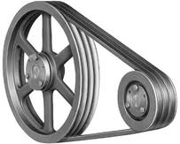
Figure 2.10.1.1–A: Belt and Sheaves
The feedwater pump belt and sheaves connect the feedwater motor to the pump. The smaller sheave is connected to the motor shaft and the larger sheave (typically 4 times larger) to the pump shaft. The sheaves are connected to each other by rubber v-belts. The motor speed is controlled by a VFD and as the motor spins it rotates the sheaves which in turn increases or decreases the pump speed. The number of belts (typically 4-6) and the required sheave size depend on the horsepower of the motor and the size of the pump. The sheaves and belts will be surrounded by a metal belt guard to prevent objects from coming in contact with the system while it is running. There will be a hinged door or a cutout over the center of the pump sheave, and possibly also the motor sheave, in order to measure the crankshaft speed. The crankshaft speed of the pump sheave is necessary for calibrating the feedwater flow rate.
2.10.1.2 Feedwater Pump Oil Level Switch
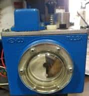
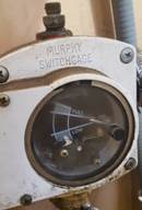
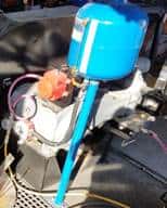
Figure 2.10.1.2–A: Pump Oil Level Switch and Reservoir
The feedwater pump oil level switch monitors the oil level in the oil reservoir. The oil reservoir is a small storage tank for the lube oil used by the feedwater pump. As the oil level in the reservoir decreases, the float inside the level switch goes down. Once the level reaches the low limit set point, the circuit is completed and an alarm is triggered that shuts the steam generator off. This oil is used to lubricate the feedwater pump internals. If the oil were to run out, the pistons would create a large amount of friction against the shafts and any gears or bearings inside the pump could wear away which would all ruin the feedwater pump. The switch can be manually tested to ensure it is working correctly by turning the needle, using the black knob on a Murphy, counterclockwise until it contacts the bottom plate or by pressing down the test knob on a Kenco style switch.
2.10.1.3 Feedwater Pump Oil Pressure Switch
Lube oil is an integral part to the feedwater pump. It keeps all the moving parts oiled and extends the life of the pump. Two main types of oil methods are used for oiling the pump. The first one is a mechanical method that is commonly called splash lubrication. A rotating dipper is attached to the pump crankshaft. Each time it rotates it passes through an oil filled trough where it picks up oil and splashes it on the necessary parts. However, this is not a precise method and does not work as well for larger pumps. On larger pumps, some parts may not get enough oil using splash lubrication. The second method is pressure lubrication. A lube oil pump is installed external to the feedwater pump. This oil pump is then used to distribute the oil directly to key areas of the pump in order to more effectively lubricate it. When a lube oil pump is installed, a feedwater pump oil pressure switch may also be installed. This pressure switch ensures that the lube oil pump pressure is not too high or too low.
2.10.1.4 Feedwater Pump Vibration Switch
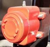
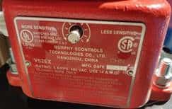
Figure 2.10.1.4–A: Pump Vibration Switch
The feedwater pump vibration switch is used to sense vibration levels of the pump and shut down the generator if the pump is vibrating too much, which can cause damage to the pump. The vibration switch consists of a magnet mounted on a spring-loaded lever arm that is attached to mechanically activated electrical switch contacts. Above the magnet is an adjustable magnetic plate. The switch is held in place by the magnetic force between the magnet and the plate, which overcomes the force in the spring-loaded arm. The gap between these two pieces can be manually adjusted using the set screw on the top exterior side of the switch. Turning the set screw to “More Sensitive” increases the gap and turning it to “Less Sensitive” decreases the gap.
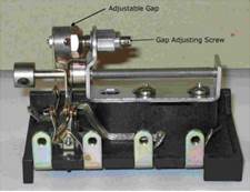
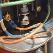
Figure 2.10.1.4–B: Set Switch
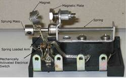
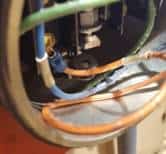
Figure 2.10.1.4–C: Pump Vibration Switch: Tripped Switch
When vibration occurs, the magnet on the spring-loaded arm generates inertial forces that oppose the magnetic force holding the switch closed. Once the vibration generates an inertial force greater than the magnetic force, the switch trips and will remain tripped until reset. To reset the switch, press the pushbutton on the bottom side of the switch (opposite side of the set screw) this will manually push the magnet back into place with the magnetic plate. The vibration switch can be tested to ensure it is functioning properly by hitting the exterior of the switch with a hand or tool to make sure it trips.
2.10.2 Discharge Dampener
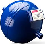
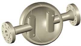
Figure 2.10.2–A: Zero Maintenance Pulsation Dampener
Upon exiting the feedwater pump, the water travels through a discharge pulsation dampener. This dampener works in the same manner as the inlet stabilizer but is built for high pressures and helps to maintain the structure of the piping after the pump rather than the pump itself. For very high-pressure systems, a pressure vessel dampener, also called a “zero maintenance” dampener, may be used instead. These are spherical dampeners that have no moving parts. This style of dampener causes the flow inside to spin which creates a smoothing effect that dampens surges from the amplified source. It can also partially rely on the compressibility of the fluid passing through it to absorb pressure fluctuations.
2.10.3 Shutoff and Check Valve
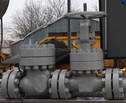
Figure 2.10.3–A: Feedwater Shutoff and Check Valves
After leaving the discharge dampener, the water travels through the feedwater manual shutoff valve and check valve. The manual shutoff valve is used to isolate the upstream side of the feedwater line for maintenance purposes while still keeping the downstream side pressurized. The check valve prevents water from flowing back into the pump when the pump shuts down. See Section 2.4 for more information on check valves.
2.10.4 Feedwater Pre-Heater
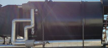
Figure 2.10.4–A: Feedwater Pre-heater
After leaving the check valve, the water travels through the pre-heater. The pre-heater heats the water to an acceptable temperature before it enters the convection section by using part of the water that exits the convection section. If the temperature entering the convection is too low it can cause condensation to form on the finned tubes which can rust the fins and inhibit heat transfer. At the exit of the convection section are two balance valves, however, some generators may only have one valve. These valves are used to divert the correct amount of hot water through the pre-heater in order to raise the temperature of the inlet water.
2.11 Flue Gas Recirculation (FGR)
FGR takes gas exiting the exhaust stack and circulates it back to the front of the generator where it is mixed with incoming combustion air. The mixture then passes through the burner for combustion. FGR is used for lowering NOx emissions in two ways. Firstly, mixing flue gas with combustion air lowers the oxygen content of the mixture which hinders the formation of NOx components since there is not an abundance of O2 present. Secondly, flue gas is mostly CO2 and inert N2. Adding these back into the combustion process lowers the peak flame temperature. Since NOx components are rapidly formed at high temperatures, lowering the flame temperature greatly reduces the formation of them.
2.12 Fuel Gas Main Train
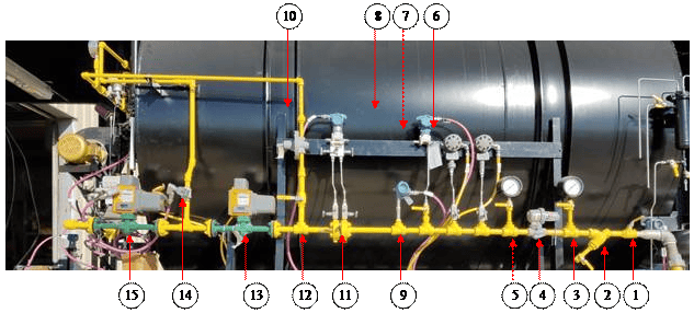
Figure 2.12–A: Fuel Gas Main Train
- Main Shut Off Valve
- Y-Strainer
- Upstream Regulator Pressure Gauge
- Pressure Regulator
- Downstream Regulator Pressure Gauge
- High Pressure Switch
- Low Pressure Switch
- Pressure Transmitter
- Temperature Transmitter
- Differential Pressure Transmitter
- Orifice Plate
- Pilot Line Diversion
- Block Valve
- Vent Valve
- Safety Valve
The fuel gas train includes all components between the burner and where the gas line attaches to the generator skid. All gas line piping should be painted yellow. Starting from where the gas line is attached; there will be a manual valve, typically a ball valve, which is used to shut off all gas to the gas line. After initial setup of the generator, this valve is typically only closed if maintenance needs to be done on the gas train.
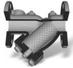
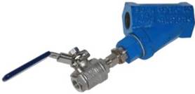
Figure 2.12–B: Y-Strainer
The gas will pass through the main shutoff valve and enter a strainer. The incoming gas line may be filled with debris such as sediment, rust, or pipe scale which can be damaging to the downstream components. A y-strainer (named because of its shape) is used to mechanically remove small solids from the incoming gas. Inside the strainer is a cylindrical metal mesh screen tube. The gas enters the strainer, passes through the screen, and exits through the other side. Any debris in the gas is trapped by the screen tube and settles to the bottom of the Y arm. The bottom of the Y arm contains a removable side which is necessary for disassembling the strainer to clean out the screen. However, most y-strainers will have a blow down attachment which is a short pipe and valve threaded onto the removable side. Opening this valve while the gas line is pressurized will blow out any of the debris without having to shut down the generator.
Upon leaving the strainer, the gas will enter the main regulator, which is used to reduce the gas pressure to the lower pressure needed for downstream service (typically 30-45 PSI). The size of the regulator depends on the flow rate of gas and the upstream gas pressure. A regulator is made up of three parts: restricting element, loading element, and measuring element. The restricting element is a valve that can provide a variable restriction to the flow. The loading element is a part that can apply the needed force to the restricting element and is typically a spring. The measuring element determines when the inlet flow is equal to the outlet flow and is typically a diaphragm.
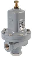
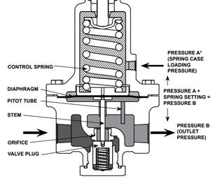
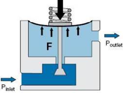
Figure 2.12–C: Single Stage Regulator
Regulators come in both single and double stages. For a single stage regulator, gas enters the regulator and flows through the opening above the valve plug. As the pressure in the body of the regulator increases, the upward force exerted on diaphragm increases which compresses the top spring and raises the valve plug. This limits the flow allowed into the body thus reducing the pressure. Turning the set screw clockwise would increase the control spring tension and increase the maximum pressure allowed in the body. Turning the set screw counterclockwise would have the opposite effect and lower the allowed pressure.
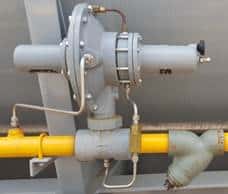
Figure 2.12–D: Double Stage Regulator
A double stage regulator is essentially two single stage regulators put together. Gas enters the first chamber (pilot) which is controlled by a factory set screw that cannot be changed. This works as an initial pressure reducer. The gas then travels into the secondary chamber which can by varied using the operator set screw. Double stage regulators are used when the outlet pressure needs to remain constant for a long time. A single stage regulator will increase/ decrease the outlet pressure if the inlet pressure raises/drops which means that it needs to be reset manually, whereas a double stage regulator will be able to maintain a constant outlet pressure regardless of fluctuations at the inlet.
After leaving the regulator, the gas will pass through a pressure gauge, low pressure switch, high pressure switch, pressure transmitter, temperature transmitter, and differential pressure transmitter and orifice plate. Each unit may be slightly different as there is not a standard required configuration, but each generator should have each of these. The pressure gauge is typically right after the regulator since there is no visual gauge on gas regulators that tells the actual gas pressure.
The high- and low-pressure switches should be set to within the limits of the downstream equipment. Sometimes these two switches are contained within a dual high/low switch instead of two separate switches. The low-pressure switch indicates problems upstream of the switch. This could be something like a closed valve or clogged strainer. The high-pressure switch protects the downstream equipment from over pressurization. A valve diaphragm can burst if the valve receives a pressure higher than what it is rated for. If the burner receives gas at too high a pressure, it can overheat or ruin some of the internal components.
The pressure, temperature, and differential pressure transmitters are all necessary components for measuring the gas flow. Without all three of these, the PLC would not have a reference for flow and could not correctly control the fuel control valve. However, a fuel gas flow meter can be installed instead of the differential pressure transmitter and orifice plate. In this case, the flow is measured directly with the device instead of being calculated so the DTP, PT, and TT are not necessary.
After the DPT or flow meter, the gas will split off in two directions. One line will continue as the main fuel line and the other will reduce to a smaller pilot line. The pilot line is covered in Section 2.13. For the main line, the gas will pass through the block and safety valves. These are both normally closed valves that work in conjunction with the flame safeguard. They will stay closed until the main flame is called to light, at which point both will open and gas will pass through to the fuel control valve and burner. If the flame goes out or a shutdown alarm occurs, these valves will slam shut.
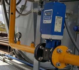
Figure 2.12–E: Fuel Flow Control Valve
These two valves are used to prevent gas from entering the burner when there is no flame. Without these, the flame could go out and the radiant section would fill with gas which would create an explosion hazard upon relighting the burner. The safety valve is used as a backup in case the block valve fails. In between these two valves will be a vent line with a valve on it. The vent valve is a normally open solenoid that is used to send any gas in between the block and safety valve to atmosphere while they are closed. After the gas leaves the safety valve, it enters the fuel flow control valve and lastly passes through to the bottom of the burner.
2.13 Fuel Gas Pilot Train
The pilot fuel train splits from the main fuel train between the differential pressure transmitter (gas flow meter) and the main block valve. The pilot line is easily distinguished from the main line by the reduction in pipe size (typically 2” down to ½”). The gas will enter the pilot high stage regulator where the pressure will be reduced to the acceptable range for the low stage regulator. The gas will then pass through a pressure gauge, the pilot low stage regulator, and enter the pilot block valve. The safety system used for the main gas line is also applied to the pilot line. This includes a block valve, safety valve, and a vent valve in-between the two. However, all three valves are simply solenoids due to the low flow rate of gas passing through rather than large shutoff valves like the main line.
Upon exiting the safety valve, the gas will typically pass by a pressure gauge and then enter the pilot premixing tube to the burner. The premixing tube has an inlet for the pilot gas and air supply. The pilot air supply is typically a tube or pipe that draws in air from the combustion air supply. The gas/ air mixture then passes by the spark ignitor where it is ignited and sent through the pilot flame tube and flame extender into the burner throat. The flame extender will stick out through one of the burner fuel ports on the fuel distribution ring.
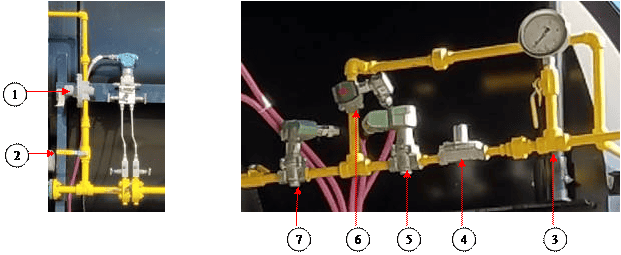
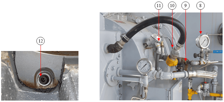
Figure 2.13–A: Fuel Gas Pilot Train
- Manual Shutoff Valve
- High Stage Regulator
- Upstream Pressure Gauge
- Low Stage Regulator
- Block Valve
- Vent Valve
- Safety Valve
- Downstream Pressure Gauge
- Gas Inlet to Mixing Tube
- Air Inlet to Mixing Tube
- Spark Ignitor
- Flame Extender
2.14 Fuel Oil Train
Optional:
- Heavy Oil Electric Heater
- Heavy Oil Steam Heater
- Fuel Oil Transfer Pump
- Fuel Oil High Pressure Switch
- Fuel Oil Low Pressure Switch
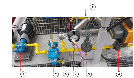
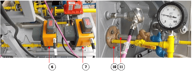
Figure 2.14–A: Fuel Oil Train
- Burner Feed pump
- Duplex Strainer
- Temperature Transmitter (Optional)
- Pressure Gauge
- Pressure Regulator
- Block Valve
- Safety Valve
- Flow Control Valve
- Coriolis Flow Meter
- Oil Inlet to Burner
- Atomization Air/Steam Inlet to Burner
The fuel oil train includes all components between the burner and where the oil line attaches to the generator skid. However, depending on the type of oil and the climate, an oil heater and transfer pump may be located away from the generator. The oil heater decreases the viscosity of the oil allowing it to flow easier, and the transfer pump moves the oil from the heater to the oil inlet on the steam generator skid. The oil heater can be either fully electric or maybe both electric and steam operated. For an electric and steam heater, the heat will initially be supplied electrically and then will switch over to steam once the generator starts producing quality steam.
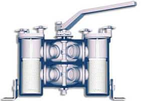
Figure 2.14–B: Duplex Basket Strainer
As with the gas train, the fuel oil train begins with a manual shutoff valve (typically a ball valve). The oil then passes through the burner feed pump which pressurizes the oil and sends it through a duplex basket strainer. Each side of the strainer has a mesh basket that catches any debris and allows the oil to flow through. The handle on the top of the strainer diverts the flow of oil to a single side, which allows the strainer to be cleaned without shutting off the oil. The bottom of each side will have a small valve that can be used to drain out any remaining oil from a side when it needs to be cleaned. The strainer can be cleaned by diverting the flow to the opposite side, opening the drain valve, removing the top on the side to be cleaned, and taking out the basket.
After leaving the strainer, the oil will pass through a temperature transmitter, pressure gauge or transmitter, pressure regulator, and possibly a high and/or low-pressure switch. The temperature and pressure transmitters are not mandatory components as the flow of oil is not a calculation based on these values like water and gas flow are. The regulator is used to maintain back pressure and reduce the oil pressure to the requirements for the burner. The oil then passes through the block valve, safety valve, control valve, and enters the Coriolis flow meter. Unlike the gas line, the oil train will not have a vent line and valve in-between the block and safety valves. Upon leaving the flow meter, the oil will enter the burner through a small plate that also contains the inlet for the air/steam atomization piping. Oil piping will most commonly be painted yellow, but may also be red.
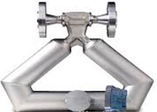
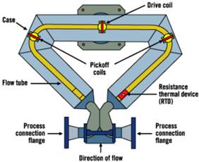
Figure 2.14–C: Coriolis Flow Meter
A Coriolis flow meter measures the mass flow of a fluid or gas by using the principles of the Coriolis Effect. The Coriolis Effect refers to the apparent effect on the motion of an object passing over a rotating frame of reference when viewed from the perspective of the point of origin of that moving object. An example of this effect can be modeled by looking at throwing a ball from the North Pole to the Equator. Although the ball travels in a straight line, to the perspective of the thrower the projected path of ball appears to curve due to the rotation of the Earth.
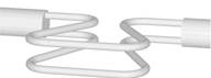
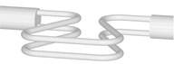
Figure 2.14–D: Movement without Flow
Instead of having a rotating frame of reference, Coriolis meters work on the principle that the inertia created by fluid flowing through an oscillating tube causes the tube to twist in proportion to the mass flow rate. Inside the Coriolis meter are two tubes. These tubes have a magnetic coil that causes them to vibrate and bend in opposition to each other. Sensors made up of a magnet and coil assembly are mounted on the inlet and outlet of each tube. The magnets create a magnetic field and when the coils move through the field, they create a voltage in the form of a sine wave. When there is no mass flow, the motion of the two tubes is symmetrical. When there is mass flow, the two vibrations are out of sync. The two vibrations are shifted in phase with respect to each other and the degree of phase-shift is a measure of the amount of mass that is flowing through the tubes.
Figure 2.14–E: Movement with Flow
2.15 Generator Cab
Includes:
- Generator Alarm Beacon
- Generator Cab Light Switch
- Generator Shutdown Beacon
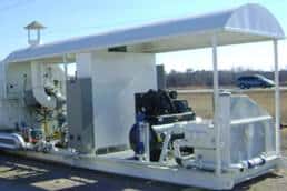
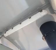
Figure 2.11–A: Cab and Lights
The steam generator cab is the area under the canopy which includes the burner, main control panel, feedwater pump and ancillary equipment, and feedwater motor. Some units may also have air compressors in this location. Steam generators that are outside or inside of a building without lighting may have cab lights. These are lights that are located on the underside of the canopy which are used to illuminate the cab area. There will be a cab light switch near the control panel if lights are present. Some generators may also contain a shutdown or alarm beacon. Both will be loud horns and may also include a colored or flashing light. The shutdown beacon will sound whenever the generator is tripped by a shutdown alarm and the alarm beacon will sound whenever a non-shutdown alarm occurs.
2.16 Generator Steam and Vent Valves
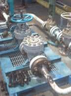
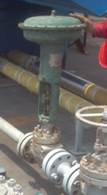
Figure 2.12–A: Manual and Vent Valve
Before steam enters the well, it will pass through the generator pressure control valve, steam manual valve, and a check valve. The steam manual valve is used to isolate the generator from the well. The vent valve is used during start up and shut down to divert low quality steam or water away from the well. This valve can either be a manual valve or an automatic control valve. When a manual valve is used, an operator will need to slowly close the vent valve once quality is reached. When an automatic control valve is used, the valve will automatically close itself once quality is reached.
2.17 Orifice Plate

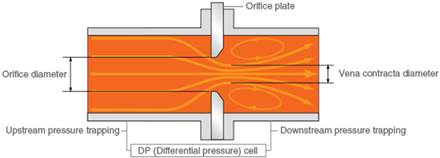
Figure 2.17–A: Orifice Plate
Orifice plates are thin metal plates with a machined circular and concentric bore, a sharp edge on the upstream side, and a beveled edge on the downstream side. The circular portion is wedged between two orifice flanges, each of which contain a flange tap for the DPT and is used for measuring the flow rate of a fluid passing through it based on Bernoulli’s equation. Bernoulli’s equation states that the pressure drop across a constriction is proportional to the square of the flow rate. To preserve the pipe size, an orifice plate is used to constrict the flow and provide a pressure differential. As a fluid flows through the orifice constriction, it is forced to converge which increases its velocity and decreases the downstream pressure. The location of maximum velocity and minimum pressure is known as the vena contracta. After that point the fluid expands, the velocity falls, and the pressure increases.
Each orifice plate will have one beveled edge which must be pointing downstream when installed. Installing a plate backwards can create significant error (12-17%) in the flow rate calculation resulting in understated volumes. The amount of beveling required on plates of the same thickness decreases as the pipe diameter increases. This means that smaller diameter pipe sizes like the ones used for water and gas on a steam generator are more susceptible to larger errors when an orifice plate is installed incorrectly. A backwards installed orifice plate records a smaller differential pressure because it takes less energy to push a gas through a hole with a beveled edge than one with a square edge (no bevel).
2.18 Quality Sample Condenser
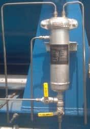
Figure 2.18–A: Quality Sample Condensor
The quality sample condenser is used to cool a portion of the water exiting the steam separator in order to take a TDS meter reading. This reading is used in conjunction with a TDS reading of a sample of feedwater to estimate the current quality that is being produced and make any calibration adjustments if necessary. The sample condenser will typically consist of a vessel which will fill with cool feedwater. This vessel will have a coiled tube inside which will have the hot water from the steam separator running through it.
2.19 Radiant Section
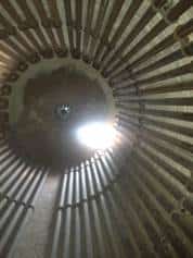
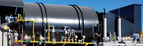
Figure 2.19–A: Radiant Section
The radiant section is made up of the radiant shell and the tubes inside. The radiant section is located in-between the burner throat and the inlet to the convection section and is used to capture heat directly from the burner flame and transfer it to the incoming feedwater through radiant and conductive heat transfer. The radiant section typically contributes 65-85% of the total absorbed heat for the steam generator. Radiant heat transfer is electromagnetic radiation generated by the thermal motion of charged particles in matter. Radiation refers to the emission of energy in rays or waves, and heat moves through space as energy waves. As the flame burns, radiant heat is transferred to the exterior of the pipes lining the inside wall of the radiant section. This heat then penetrates the pipe wall through conduction and transfers the heat (energy) to the water inside.
Unlike with the convection section, none of the radiant section tubes are finned. Since the fins are thin metal to maximize surface area, being directly next to a high temperature open flame would overheat the fins and cause them to melt. This is the same reason why bare tubes are used as “shock tubes” at the inlet to the convection section. Hot water exits the convection section, passes through the bypass valve, and joins the water exiting the feedwater pre-heater before entering the radiant piping. As the water flows back and forth through the entire radiant coil, it will absorb heat and rise in temperature. Once the water reaches the saturation temperature for the pressure that it is under, it will start to vaporize and create a two-phase region of water and steam. The water will stay in two phases as long as the saturation temperature is maintained.

Figure 2.19–B: Tube Skin Thermocouple
The goal for most generators is to maintain saturation and produce a quality of 80%, meaning that 80% of the water has turned to steam and 20% remains as a liquid. If the temperature were to rise without the pressure also rising, the water would pass the saturation point and fully vaporize to create superheated steam. Superheated steam is extremely dangerous for a steam generator because steam carries an immense amount of thermal energy. This energy is transferred to the interior wall of the pipes, but the excess water in saturated steam helps to insulate and carry part of this heat away from the pipe walls. If superheated steam is formed, then there is no water barrier to carry away the excess heat and it is heavily transferred to the pipe walls which can cause them to overheat and burst. To prevent the tubes from overheating in this situation, there is a radiant tube temperature sensor installed on the radiant piping just before it exits the radiant section. This thermocouple measures the skin temperature of the pipe using a special welded tip. The tip looks like a metal rectangle welded to the outside of the pipe wall that is attached to a long probe that extends outside the radiant wall. There may also be a thermocouple of the same style directly on the pipe after it exits the radiant chamber.
Figure 2.19–C: Manway
The radiant section will typically have a sight port, u-tube manometer, and manway on the burner end plate. The sight port allows operators to view the flame as well as monitor the overall condition of the tubes inside, the u-tube manometer measures the differential pressure of the radiant chamber, and the man way is a removable door that allows for maintenance to enter the radiant chamber.
2.20 Refractory
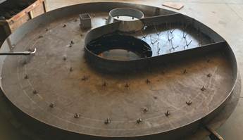
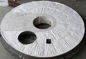
Figure 2.20–A: Cast and Module Refractory
Refractory is any non-metallic material having chemical and physical properties suitable for withstanding continuous exposure to environments above 1,000 °F. Steam generators use two types of refractories; cast and fiber. Cast refractory is poured in a similar manner to concrete. It comes in bags of aggregate and is mixed with water to create semi-solid slurry. The slurry mixture is then poured and packed into a mold where it sets to dry and harden. Refractory anchors are welded to the base of the material where the refractory is being poured in order to give the refractory extra strength. This is similar to using rebar for concrete.
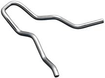
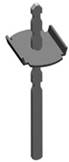
Figure 2.20–B: Cast and Fiber Sheet Anchors
Fiber refractory is similar to house wall insulation and comes in either sheets or modules. Sheets of refractory come in rolls that are cut to length and installed over stud anchors to keep them in place. In order to retain the most heat, sheets are typically stacked and pressed together to obtain a certain density of material. The alternative to fiber sheets is premade modules. These modules are layers of fiber sheets that are folded over each other to produce a certain density of material. A different style of stud is installed for modules, which looks like the threaded part of a bolt welded to a square base. The center of each module has a hole with a metal bracket on one side. The bracket goes over the stud and then a nut is screwed onto the bolt to hold the module in place. An H-anchor, or other reinforcement anchor, can be installed between modules to help hold them together.
As cast refractory heats up, it soaks in heat from the flame and retains this heat allowing for a more consistent temperature profile once the walls reach equilibrium. However, cast refractory is hard to replace if it becomes cracked or breaks. Because of this, cast refractory is typically only used in places where liquids may contact the refractory or where it is not practical to use fiber due to space restrictions. Cast refractory is commonly used on the convection section tubes sheets, the drip ledge directly under the burner throat in the radiant section, and on the floor of the radiant section for a drain pathway.
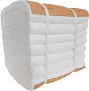
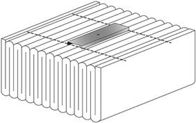
Figure 2.20–C: Fiber Modules
Fiber refractory is used any place it can be easily installed due to its ease of replacement. If a portion of modules is destroyed, they can be individually replaced quickly reducing downtime and maintenance cost. Another advantage with using fiber overcast is that fiber does not require a soak time and heats the radiant much faster. However, fiber refractory is more prone to temperature fluctuations.
2.21 Safety Relief Valves
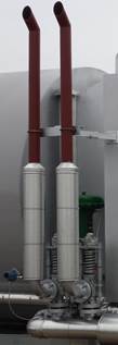
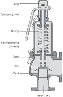
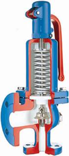
Figure 2.21–A: Safety Relief Valves
A safety relief valve, also known as a pressure relief or safety valve, is a type of safety device used to control or limit the pressure in a system which might otherwise build up and cause damage to the steam generator. The standard spring-loaded safety valve is a self-acting device consisting of a right angle pattern valve body with an inlet connection mounted on the pressure containing system.
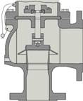
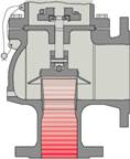
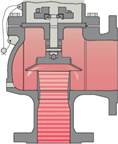
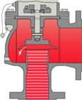
Figure 2.21–B: Relief Valve Working Principle
During normal operation, a fluid or gas passes by the safety valve and fills only the inlet tract. The spring is set to a certain resistance which correlates to a pressure rating. As the pressure of the fluid reaches the maximum pressure allowed by the spring tension, the spring will contract and raise the disc off the seat, which increases the spring force. This means that the pressure would have to continue to rise before any further lift can occur and for there to be any significant flow through the valve. The additional pressure required before the valve discharges at its rated capacity is called the overpressure.
To open fully from this small overpressure, the disc typically has a shroud around it. As fluid begins to flow into the control chamber, the shroud creates a larger area for the fluid to push against. The shroud also redirects the fluid downward. The combined effects of these two factors overcompensate for the spring force as it contracts and allows the valve to open fully from a small over pressurization. Once the pressure in the system is reduced, there is not enough force to overcome the spring force and the valve closes itself. Safety relief valves will be located on the feedwater pump, the steam atomization knockout drum, and two will be on the steam line between the outlet of the radiant section and the generator pressure control valve. The two safety valves on the steam line are commonly on, or right before, the steam separator.
2.22 Steam Separator
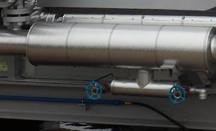
Figure 2.22–A: Steam Separator
The steam separator is located in between the exit of the radiant section and the steam DPT and is used for separating entrained water from wet steam to output 100% quality steam to the well. Water is an unwanted product when injecting a well and without a steam separator, both water and steam will enter the well. Water has a much lower enthalpy than steam at the same temperature and pressure, and for systems with a constant pressure, the heat absorbed and released is equal to the change in enthalpy. Since steam has a higher enthalpy than water, it is able to carry more heat to release into the well.
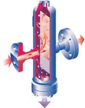
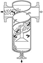
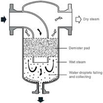
Figure 2.22–B: Baffle, Cyclonic, and Coalescence Separators
The three most common types of separators used are baffle, cyclonic, and coalescence separators. A baffle separator consists of several baffle plates which cause the steam to change direction as it passes through the separator body. The entrained water has a greater mass and inertia than the steam, thus, when there is a change in flow direction, the dry steam flows around the baffles and the water droplets collect on them. A cyclonic separator uses a series of fins to create a high-speed cyclonic flow. The velocity of the steam causes it to swirl around the body of the separator. This causes the heavier water droplets to fall out of suspension and hit the walls where they collect and flow to the drain. A coalescence separator forces the steam flow through a mesh pad, also called a demister pad. The demister catches the water droplets as steam flows through it. The droplets increase in size until they are too heavy and fall to the bottom of the separator.
The bottom of the separator will lead to a pipe with two valves. The first valve (quality sample line valve) will have a compression connection with metal tubing that goes to the steam inlet of the quality sample condenser. The second valve (blowdown valve) will have a short connection pipe and is used for purging the separator from buildup before the sample condenser line is opened. This is necessary because buildup in the separator piping could clog the quality sample line due to its small diameter.
2.23 Steam Traps
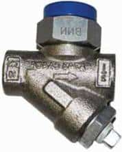
Figure 2.23–A: Steam Traps
Steam traps are used to discharge condensate while retaining live steam in the system. This allows pure steam to flow through pipes and equipment. Without a steam trap, condensate droplets in the steam can cause poor heat transfer and damage to process equipment. There are three main types of steam traps: thermostatic, mechanical, and thermodynamic. Thermostatic steam traps work off of the temperature of the fluid. Inside the trap is a temperature sensing element. Initially as air and condensate flow through, the element is cooled and remains open. Once steam starts flowing and heats the element, it causes the valve inside to pull towards the seat and close off any flow. While the trap is closed, any condensate will accumulate around the element and cool it. Once the element is sufficiently cooled by condensate, it will open and drain.
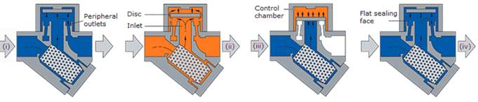
Figure 2.23–B: Thermodynamic Steam Trap
A mechanical steam trap has a float inside that raises and lowers to open the valve. As condensate accumulates inside the trap, the float will float on top of the water and rise with the level of the water present. Eventually the float will reach a point where it will open the valve and all the condensate will be drained. The body of the trap will then fill with steam and the float will drop down and close the valve since it cannot float on steam. The last and most common for steam generators is the thermodynamic trap, also sometimes referred to as a disc trap. Inside the thermodynamic trap is a disc that covers a hole in the outlet of the valve. Before steam is made, water and air force the disc up away from the hole and flow through the valve outlet. As steam is produced, it fills the cavity above the disc and pushes it down until the outlet hole is covered. Over time the inlet cavity will fill with condensate while the steam continues to apply a downward force on the disc. The steam in the chamber above the disc will eventually begin to cool and condense, at which point the upward force from the condensate will exceed the downward force on the disc and the disc will lift and drain the valve.
2.24 TDS Meter
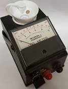
Figure 2.24–A: TDS Meter
A TDS meter (also called a conductivity meter) is used to measure the total dissolved solids (TDS) in a liquid. TDS is a combination of all organic and inorganic substances contained (dissolved) in a liquid in molecular, ionized, or micro-granular form. Solid sizes present are small enough to pass through the water filtration upstream of the generator which is used to reduce the hardness of the water. As water turns to steam the dissolved solids do not evaporate and instead stay in the remaining water in the system that has not vaporized. A sample of water is taken from the steam line and referenced against the inlet feedwater. Since the steam line is only now partially liquid water and all the dissolved solids are within the liquid, the concentration of dissolved solids is higher than in the inlet feedwater. Estimated steam quality can then be calculated from these two values.
2.25 Temperature Sensors
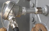
Figure 2.25–A: Temperature Sensor
Temperature sensors are used throughout the steam generator for helping to calculate flow rates and monitoring and protecting the generator from high temperature scenarios. Temperature sensors used can come in two different styles which include resistive temperature devices (RTDs) and thermocouples (TCs). A RTD measures the electrical resistance between metals whose resistance is a function of temperature. A thermocouple consists of two dissimilar metals joined at one end. When the junction of the two metals is heated or cooled a voltage is produced that can be correlated to temperature.
2.26 Thermal Mass Meter
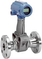
Figure 2.26–A: Thermal Mass Meter
Thermal mass meters measure the flow rate of gases and liquids based off of the convective heat transfer properties of the fluid. These meters can be used as an alternative to using a PT, DPT, and TT to calculate the fuel gas flow rate. Each thermal mass meter contains a heat source with an RTD or other temperature sensor on both sides and measure the flow in one of two ways. The first is by introducing a constant amount of heat into the flowing stream and measuring the associated temperature change. The second is by maintaining a constant temperature difference between the sensors and measuring the heater energy that is required to do so.
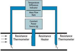
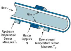
Figure 2.26–A: Immersion and External Thermal Mass Meters
Thermal mass meters typically come in two styles: immersion and externally heated. Immersion heaters place the heat source and temperature sensors within the pipe and use the first measurement method described above. Externally heated thermal mass meters have the heat source and temperature sensors mounted to the outside of the pipe. This style is more commonly used for corrosive fluids and gases or fluids which would create a coating effect and inhibit correct measurement. However, mounting the sensors externally slows the response rate of the sensors and makes the measuring process nonlinear. This is because the heat introduced is distributed over a portion of the pipe’s surface and transferred to the process fluid at different rates along the length of the pipe.
2.27 Turbine Flow Meter
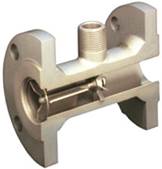
Figure 2.27–A: Turbine Meter
A turbine flow meter is used to measure the volumetric flow of a fluid and is an alternative option to the coriolis meter for measuring fuel oil flow rate. As fluid flows through the turbine meter, it impinges upon the turbine blades that are free to rotate about an axis along the center line of the turbine housing. The angular velocity of the turbine meter is directly proportional to the fluid velocity.
2.28 U-Tube Manometer
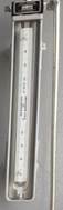
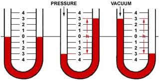
Figure 2.28–A: Manometer
On a steam generator a u-tube manometer is used to measure the radiant section air pressure directly after the burner and is located on the burner end plate. A u-tube manometer is a simple measuring device that functions on the displacement of a fluid due to an applied force. By design, the manometer is a single glass tube in a “u” shape that is typically filled with mercury, oil, or water. The fluid is filled to the zero line on the measuring template located in between the two tube sides. As the pressure raises or drops, it displaces one side of the fluid depending on whether the pressure is positive or negative (vacuum).
2.29 Water Softener
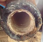
Figure 2.29–A: Hard Water Scale
Water softening is a process that removes minerals, such as calcium, magnesium, and lime; from water to reduce scale buildup in the steam generator. Without this process, water with high levels of calcium can clog the pipes with the buildup left behind as the water turns to steam. A water softener is made up of a series of control valves, mineral tanks, and a brine tank. The control valves are used to guide the water down the correct path as it passes through the mineral tanks. The mineral tanks which include a filter, a softener, and a polisher are filled with plastic beads commonly made of polystyrene. These beads create an ion-exchange column as they are negatively charged, and magnesium and calcium are positively charged. The brine tank contains a solution of water and either salt or potassium which is used to regenerate the beads in the mineral tanks.
The beads within the tanks originally contained a sodium ion bonded to the negatively charged beads. As water with magnesium and calcium passes through the beads, the monovalent sodium (Na+) cations are replaced (exchanged) with the divalent magnesium (Mg2+) and calcium (Ca2+) cations since the divalent cations bond more strongly. When all the available sodium ions have been replaced, the beads must be recharged by eluting the magnesium and calcium with the brine solution. The first tank (filter) is cleared only by reversing the flow of water while the other two tanks (softener and polisher) reverse the flow of water, but also pass the brine solution through them. Even though sodium is a weaker cation than magnesium and calcium, the high concentration in the brine solution allows the sodium to replace the magnesium and calcium on the beads. This solution is then flushed out of the tanks through a drain valve and the softening process restarts. Most industrial water softener systems will have at least two sets of mineral tanks and one brine tank. This allows three of the mineral tanks to be softening water while the other three are being regenerated allowing for no downtime.